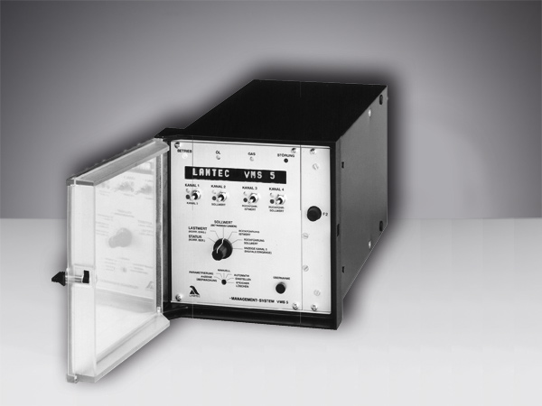
VMS

- Electronic compound, up to 5 channels
- Mixed combustion with up to 2 out of 3 fuels
with flying change - Connects to control system
- Simple to program
- 10-bit resolution
- Can be operated from PC
- Optional load regulator
- Integrated O2 controller
- Type-examination tested
| Power supply: | 230 VAC +10 % -15 % 50/60 Hz 115 VAC +10 % -15 % 50/60 Hz (optional) |
| Ambient temperature Operation: | +0 °C … +60 °C |
| Ambient temperature Transport and storage: | -25 °C … +60 °C |
| Resolution per analogue input: | 999 digit, 10 bit |
| Three-point step Recommended run time of the servomotor: | 30 s … 60 s |
| Continuous output: Apparent ohmic resistance: | 0 … 10 V > 5 kΩ 0/4 … 20 mA < 600 Ω |
| Digital signal input: | 16 via floating contact 24 VDC or optional via 230 V module type 660R0018 |
| Number of curve set: | 2 per channel (e.g. for oil/gas dual-fuel burner) optional 4 or 8 |
| BUS connection: | Via 25-pole Sub-D socket BUS card for the following systems:
|
Approvals:
| EC Type Examination Certificate (Modul B), according to Directive 2014/68/EU
SIL 3 Confirmation
|
Universal electronic fuel and air ratio control unit (VMS) for all types of combustion systems. TÜV-tested, licensed for TRD 604 installations. The VMS is the VR4 ratio controller’s successor. It includes the electronic fuel and air ration control system with 4 or 5 servo outputs. The analogue inputs have 10-bit resolution. This permits actuator accuracy of < 0.1° with a 90° motor.
All operational and error messages are displayed in plain text. Up to 20 points can be input per curve. The unit’s configuration can be changed on site through password-protected parameters. In the standard configuration, the unit has 2 curve sets (e.g. for oil and gas); 4 or 8 curve sets are available as options. The options of introducing corrections have been widely extended. This further improves the ability to implement special installations.
The unit has a PC interface. Curve and parameter data can be saved by means of a Windows based program. As a result, the VMS can be remote-controlled and the curves represented graphically. A demo version of this remote control and remote display software is available at download register.
In addition, the VMS has a LAMTEC-SYSTEM-BUS interface for linking to other new-generation LAMTEC instruments, such as LT1 / LT2 Lambda transmitters for measuring the O2 content of flue gas and for optimizing combustion.
The VMS can be connected to the control system via standard bus systems.
Other features:
- The last 10 faults are stored and can be called up at any time
- Integral, fuel-referenced operating hours and start-up counter
- Direct link to a Namur sensor for measuring revolution speeds in rev. speed control systems (optional)
- Optional integral output regulator with special functions, such as start-up and shutdown capabilities and weather control
All these innovations notwithstanding, the operating method has remained the same as in the VR.
Curve input is just as simple in the VMS as in its predecessor. A graphic representation of the most important options and functions is shown in selection criteria.
| Function | Communication | Optional |
Start-up counter
|
RS232 interface • Operating Maintaining
|
CO/O2 control
|
Operating hours counter
|
LAMTEC System Bus (LSB)
|
Burner firing-rate
|
Compound regulator
|
Control instrumentation connection – • CAN Bus
|
Frequency converter
|
VISIOCONTROL |
