
Application
CMS – The next evolutionary step in combustion management
Whether standard industrial combustion or more complex process applications, the revolutionary LAMTEC CMS burner and plant management system sets new standards.
Modular: The CMS can be easily adapted to the needs of the plant. From small industrial burners to large plants, everything can be controlled.
Safe: The modules are connected via the fail-safe iLSB.
Communicative: The CMS has a Modbus TCP interface as standard. Other fieldbus modules can be connected, e.g. PROFIBUS DP, PROFINET, Modbus RTU in preparation.
Simple: The CMS supports graphic and intuitive user guidance.
Demand-oriented: Whether simple and cost-effective UI400 user interface or 7″ colour touch screen (GUI607) for more comfort – with the LAMTEC CMS you are not limited in visual output.
Versatile: Integrated soft PLC (CODESYS) for non-failsafe control tasks.
Flexible: Free assignment of burner functions to inputs and outputs in the CMS.

Technical data
System Modules
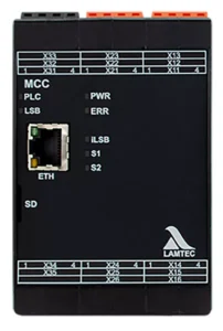
MCC
Your advantages at a glance:
- Burner sequencer
- 12 Digital Inputs, 9 digital Outputs, freely configurable
- 2 A per output, max. 8 A in total
- Input for flame sensor FFS07/08 (option)
- Input for ionisation (option)
- Firing rate input 4-20 mA/TPS or potentiometer,
Output 4-20 mA internal firing rate - CODESYS Soft PLC with access to internal variables for non-failsafe extensions
- ModbusTCP interface on-board (Ethernet)
- Versions available:
- Input 230VAC | Output 230VAC
- Input 120VAC | Output 120VAC
- Input 24VDC | Output 230VAC
- Input 24VDC | Output 120VAC
- Input 24VDC | Output 24VDC
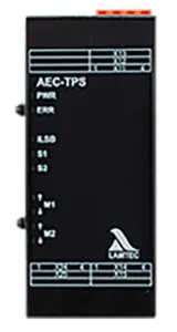
AEC-TPS
Your advantages at a glance:
- 1 Module supports 2 TPS actuators
- Current output supports up to 0,5 A per actuator
- Up to 5 AEC-TPS modules per system
- CMS actuator available from 6 Nm to 200 Nm
- Technically compatible with ETAMATIC/FMS actuators (type approval has to be checked)
- Up to 10 actuators per CMS system possible
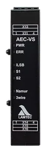
SAI
Your advantages at a glance:
- 3 failsafe analogue inputs, or 6 non-failsafe analogue inputs, or any combination possible
- All inputs are freely configurable to the functions
- Inputs: 4-20 mA, 0-10 V impulse or digital
- Up to 3 SAI per system
- Up to 9 failsafe or 18 non-failsafe inputs per CMS system possible
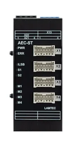
AEC-ST
Your advantages at a glance:
- Compatible to the stepper motors of the BT300
- 1 Module supports 4 stepper motors
- 0,8 Nm, 1,2 Nm, 3 Nm, 9 Nm
- 2 AEC-ST Modules per CMS system
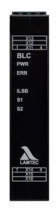
BLC
Your advantages at a glance:
- Connecting CMS modules installed at different locations
- Modules for extending the CMS internal bus via cable
- Maximum length of a bus segment 70 m
- BLC Active:
- Always located at the end of a bus connection (receiver module).
- Opens a new bus segment for the modules connected thereafter for bus lengths > 70 m
- Requires active +24V DC power supply.
- BLC Passive:
- Always located at the beginning of a bus connection (transmitter module).
- Can also be located at the end of a bus connection (receiver module). In this case, no new bus segment is started.
- Does not require a separate +24V DC power supply.
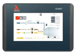
- Touchscreen
- Available in various sizes (7“ GUI607, 10“ GUI610, 15“ GUI615)
- Graphical user interface (GUI)
- Largely language-neutral
- Plant image
- Option to save backup record
- Customizable graphics according to customer specifications
- Setup assistant
- Unlimited distance to MCC (Ethernet)
- Integrated CODESYS PLC for customer-specific functions
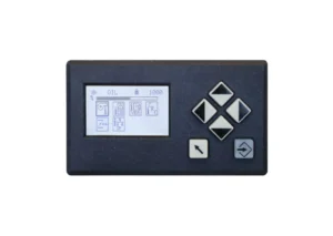
- Cost-effective User Interface
- Graphical user interface
- Language-neutral display
- Easy to use
- Connection via LAMTEC SYSTEM BUS (LSB)
- up to 500 m distance to MCC
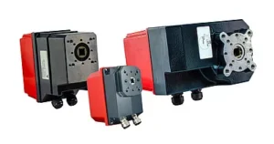
CMS actuators from TPS06 to TPS200
- from 6Nm to 200Nm
- Max 10 actuators per CMS
- 6-40Nm TÜV-certificated for use with the CMS
- 60-200Nm individual approval
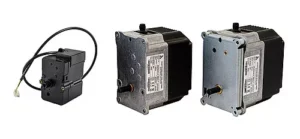
662R5X actuators (only in combination with AEC-ST module)
- from 0.8 Nm to 9 Nm
- Max. 4 actuators per module
- TÜV-certificated for use with CMS AEC-ST module and BT300
Sample Applications
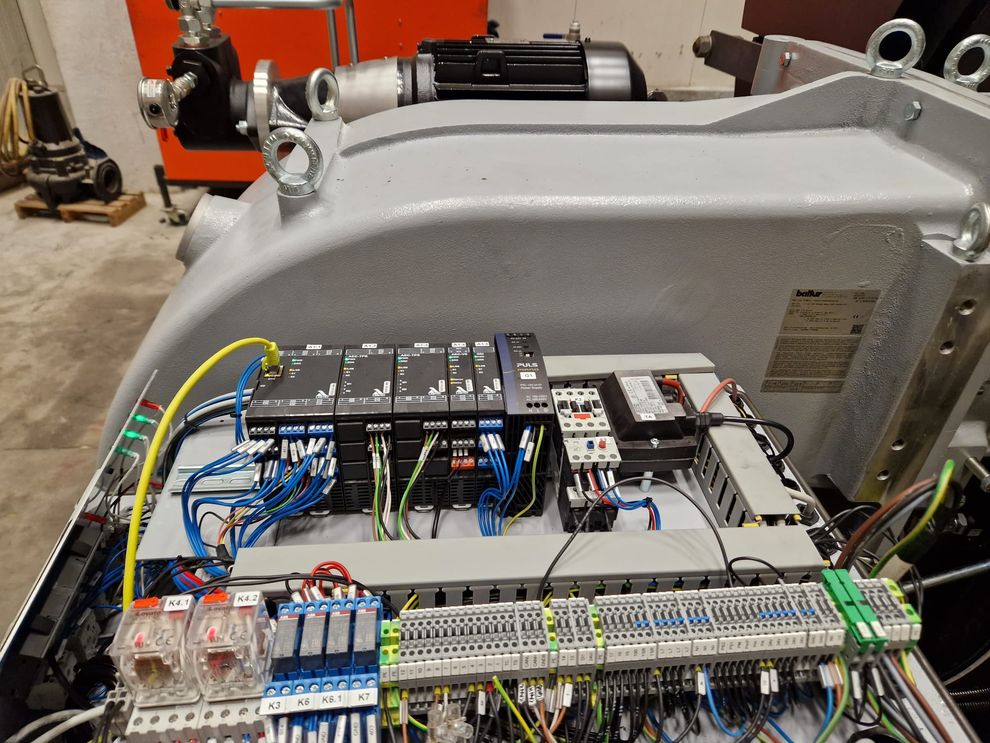
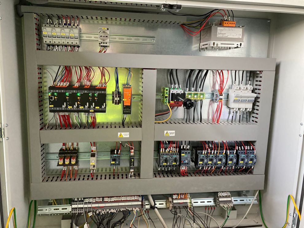
CMS on burner | CMS in control cabinet |
 |  |