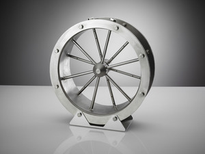
Mass Flow Measurement Grid

- Volume measurement of gaseous media in ducts, especially for comdustion air for firing applications
- With a minimum of differential pressure loss, compared to the conventional technology
- Short length of inlet- and outlet-stretch for laminar flow. Long air-ducts are not required anymore
- Stainless steel material
- Basic temperature range up to 400 °C
- Free of maintenance for use in clean air application
- Rectangular and circular grid versions are available
- With increased dust particles loading, flushing back can be done (option)
- Connection to the Differential Pressure Transmitter by impulse piping or on customer‘s request
The grids are made by specifications of the customers. Therefore the technical data can be indicated only generally. In the case of concrete offers, and/or supplies a data sheet made particularly for the appropriate grid is provided.
| Material | Stainless steel 1.4404 (other materials on request) |
| Pneumatic connection | Sleeve G1/4″ |
| Installation types |
|
| Applicable temperature range | +5°C…+400°C (other temperature ranges on request) |
| Measuring media | All not aggressive, not explosive, gaseous media with well-known density |
| System pressure | -0,5…+0,5 bar (negative/positive pressure) |
| Repetition accuracy | Generally repetition accuracy ≤ +/- 1% from measured value |
| Measuring accuracy |
|
The principle is based to the Bernoulli theory, which means, that the total kinetically energy of the flow-stream neglecting the friction, – stays the same, namely the sum of the dynamic and static pressure. The Stagnation Pressure Grid overs partially the area of the duct, so that it increases the flow-speed in reference and relation of the static pressure. This pressure is measured on special positioned openings. The on this way measured pressure difference is 2- to 3 – times higher, then the middle dynamically pressure in the duct flow-stream, for which the flow-speed has to be within of 3 and 40 m/sec.
The parallel adjusted pipes (with closed ends) build up an open grid across the duct area rectangular to the stream axis. Some of these pipes have openings to read the total pressure, other pipes are taking the reference pressure. These two pressures are feed into separate summing-pipes and also to separate connecting stubs. The pressure difference of these two values define the transmitter output signal.
standard type dimensions | Standard type dimensions |
| Selectable diameter from 100 mm to 1600 | Width x height in mm vonn 200 x 200 to 1100 x 1100 |
| Duct stretch L = 100mm | Diff. Pressure connection, on hight-sideconnection, piping stubs 12 mm |
| Material thickness 3mm | Steel sheet stiffener and counter fixing for width side dimensions > 600 mm |
| Optional: With flange and counter flange |
