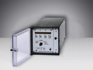
FMS

- Burner control
- Electronical compound, up to 5 channels
- Universal field bus to interface process control
- PC/Modeminterface
- Integrated load controller
- Integrated leakage test
- Integrated CO/O2 controller
- Sliding controlled fuel changed
- Simultaneous combustion of 2 fuels with variable mixture ratio
- Blow out of the burner lance
| Voltage supply: | 230 VAC +10 % -15 % 50/60 Hz 115 VAC +10 % -15 % 50/60 Hz (option) |
| Ambient temperature Operation: | +0 °C … +60 °C |
| Ambient temperature Transport and storage: | -25 °C … +60 °C |
| Resolution per analogue input: | 999 digit, 10 bit |
| Three-point-step: | Via external relay modules type 660R0013 up to 50 mA (40 Nm) type 660R0131 more than 30 Nm up to 3,1 A |
| Recommended run time of the servomotor: | 30 s … 60 s |
| Constant outputs | 0 … 10 V > 5 kΩ |
| Load: | 0/4 … 20 mA < 600 Ω |
| Digital signal inputs: | 16 via floating contact |
| Number of curve-sets: | 2 per channel (e.g. for oil/gas dual-fuel burner) optional 4 or 8 |
| BUS connection: | Via 25-pole sub-D socket, communication processor optional for the systems:
|
Approvals:
| EC Type Examination Certificate (Module B) according to Directive 2014/68/EU
SIL 3 Confirmation
CE Declaration of Confomity
Marine Type Approval Certificate GL and LR |
This is the complete burner controller that meets all requirements; type-examination tested. By using a different relay unit and a software module, the VMS compound management system becomes the FMS combustion management system. Thus, the electronic compound regulator comes with a burner controller. This integration saves a great deal in terms of wiring overheads, and reduces the number of error sources. Commissioning the system becomes simpler.
The FMS contains all VMS functions. However it also contains the combustion controller, and if necessary, a leakage monitor too. Together, all these functions reduce the required number of external instruments to a minimum, thus creating a price/performance ratio without peers. When using the FMS with integral leakage monitor, output regulator and possibly rev. speed feedback, almost everything needed for combustion control is integrated into one unit. Safety chains, sensors and monitors are linked directly to the FMS. Additional external regulators or monitoring devices are hardly needed anymore.
Visual data and operation are the same as in the VMS. Control of the magnetic valves, the ignition transformers, the ventilators etc takes place via a special relay module. This allows valves up to 2 A to be switched directly. The FMS has 16 digital inputs, of which 3 are inputs for separate safety chains. Thus, external error sources can be differentiated, identified and displayed.
The controller can be adapted to the widest range of different tasks through simple parameter settings. Many of these can be adjusted on site. Each permitted flame monitor can be addressed via a floating-potential contact.
| Function | Communication | Optional |
Start-up counter
|
RS232 interface:
|
|
Operating hours counter
|
LAMTEC System Bus (LSB)
|
|
Burner control unit
|
Control instrumentation connection –
|
|
Compound regulator
|
VISIOCONTROL
|
|
NEMS fault indicators
|
|
